


Production of a Systainer cabinet made of wood/Festool cabinet

Description
Preparation/set-up
-
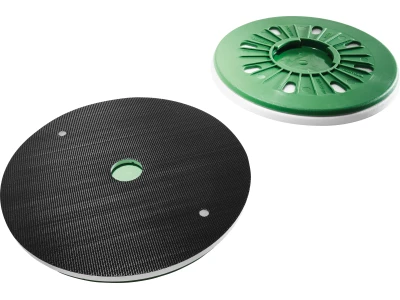
Replacing the splinter guard
To ensure optimum splinter-free panel cutting, we recommend replacing the splinter guard if necessary. The old splinter guard is removed for this. Before affixing the new splinter guard, the contact surface must be cleaned with acetone, for example. Then affix the new splinter guard with high application pressure.

-
Cutting into the splinter guard
The saw is now set to zero play on the guide rail, and the splinter guard is then cut into again.

-
Setting the parallel stop
The panel strips are cut using the parallel stop. Before starting to cut, the scale of the parallel stop should be compared with the actual cutting width. If necessary, the parallel stop must be readjusted according to the operating instructions. In the picture, the parallel stop is set to 40 cm.


Procedure
-
Panel cutting
After cutting the panel, all the required panel strips for the body parts are cut using a parallel stop and guide rail (here, strips of 40 cm in width for the body sides, centre section, bottom and top).

-
Cutting panel strips to length
The panel strips previously cut to width are now trimmed to the required length using an angle stop with mounted extension. Tip: The use of the green splinter guard enables splinter-free cuts to be made on both sides.

-
Cutting the rear wall
Cut the rear wall material using the mounted angle stop. The exact measurement is determined by the body dimensions, the panel thicknesses used and the rear wall groove in the body parts.

-
Positioning and labelling individual parts
The cut body parts, consisting of bottom, top, sides and centre section, are positioned and labelled.

-
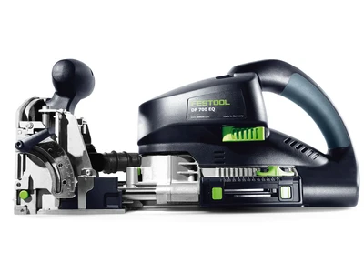
Joining body parts
The body parts should be joined using Domino dowels. To do so, the parts are first positioned and the tool is equipped with the appropriate cutter. The centre panel should be reset in the rear area here, as the rear wall should be designed to be continuous.

-
Joining the centre panel with the bottom
This step involves routing of the centre panel for the connection between the centre panel and the bottom or top. For this, the milling machine is aligned with the edge of the panel via stop catches. The milling groove in the centre is positioned on an axis marking. The process is carried out accordingly at both ends.

-
Joining the bottom/top with the centre panel
This step involves routing of the bottom or top. If it is not possible to position the Domino milling machine using the stop catches, this is done using the corresponding markings on the tool's base plate.

-
Joining the bottom/top with the sides
The milling grooves at the panel edges are produced using the angle stop. Firstly, this allows the milling machine to be guided more safely, and secondly, the movable positioning aids of the Domino milling machine or the angle stop can also be used for positioning.

-
Producing the series of holes
The sides and the centre panel should be equipped with series of holes, so that the drawer fixtures can later be flexibly installed. The position of the series of holes is adjusted to the pull-out drawers used, and should be taken from the assembly instructions. In this application example, SYS-AZ pull-out drawers are used for size M Systainers, and a pull-out drawer from Blum in conjunction with a drawer you have built yourself is used for size L Systainers. In this case, both pull-out drawers can be mounted with the same positions for the series of holes.

-
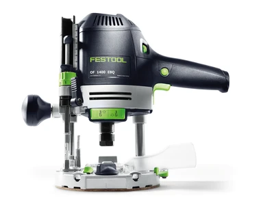
Preparing the router for producing the series of holes
The LR 32 hole drilling set is used in conjunction with the OF 1010 R router to produce the series of holes. For this, the router must first be mounted so that it is centred on the guide plate (in accordance with the operating instructions).

-
Positioning the front series of holes
Here, the front series of holes is positioned so that the distance from the front edge is 58 mm. To do so, the guide rail is aligned with the edge via the set stops. The longitudinal stop (LA-LR 32 FS) is set to 9.5 mm. After it has been aligned, the guide rail must be fixed with fastening clamps.

-
Producing the front series of holes
Once the guide rail has been aligned and fixed, the series of holes can be routed. The holes in the centre panel should be continuous, which is why the HW dowel drill (dia. 5 mm) with V-shaped tip is used, so that there are fewer splinters when piercing. If necessary, a sacrificial board can also be placed underneath to prevent splinters. The routing depth must be set accordingly for the series of holes on the side pieces (here, 13 mm). The holes should not be continuous here.

-
Producing the rear series of holes
In this example, the rear series of holes should be produced at a distance of 224 mm from the front series of holes. To do so, the guide rail is aligned with the front edge via the parallel side fences. The appropriate setting of the parallel side fences must first be determined. The setting has been marked here with a pencil line. The distance of the rear series of holes must always be set according to the fixtures used. After alignment, drill the series of holes on all parts.

-
Routing a groove for the rear wall
The rear wall gives the body stability and is necessary for correct alignment. In this example, the rear wall should be inserted into the body sides, bottom and top via a groove. Depending on how thick the rear wall is, a suitable cutter is accordingly selected and installed in the router. As a one-off, the parallel stop is appropriately adjusted to ensure efficient production of the groove in all parts to be processed.

-
Sanding edges
The visible edges of the body components should still be sanded before assembly. The edge sander is very well suited to this. Sanding was carried out here until final sanding with a grit of 180 was achieved.

-
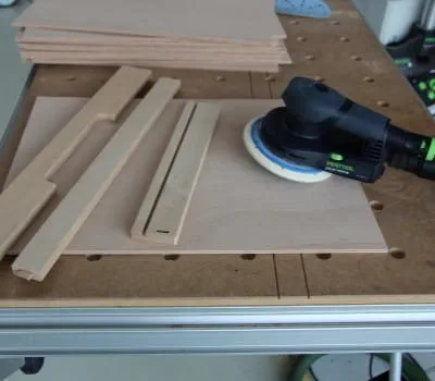
Sanding body parts
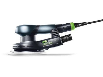
All remaining surfaces are also sanded before assembly. The ETS EC 150 eccentric sander was used here for this. Components can be fixed quickly and easily using the MFT system accessories. Where applicable, also apply a suitable surface treatment.

-
Assembling the body
The body, consisting of bottom, top, sides, centre piece and rear wall, is prepared for assembly. To this end, Dominos are glued in and adhesive is accordingly applied to the surfaces to be glued. The parts can then be put together and glued using fastening clamps.

-
Panel cutting for drawer construction
The body should be equipped with drawers. Systainer pull-out drawers (SYS-AZ) will later be installed in the left-hand section of the body, in order to stow size M Systainers. Size L Systainers should be able to be stowed in the right-hand section. Drawers are produced for these in the following steps. Firstly, the bottom of the drawer, the sides, the front piece and the rear piece are cut roughly to size. The exact measurements depend on the fixture used. The panels can be cut roughly to size with a plunge-cut saw, for example. The narrower strips are then cut in a later work step using a table saw.

-
Producing parallel cuts
The panels for the bottom, sides, rear piece and front piece that were previously cut roughly to size are cut into parallel strips on the table saw. Before cutting, the direction of the wood grain should be noted.

-
Grooving the bottom of the drawer
The bottom (here, 5 mm plywood) should be grooved into the front piece of the drawer in each case, as well as into the side pieces of the drawer. The grooves are produced with the table saw. To do so, the dust-extraction attachment is removed, the spacer wedge is pressed down (for groove cuts) and a suitable cover is installed, such as: CSC SYS 50 Quick Guide – Blade cover. Here, for example, the groove width is 5 mm (material thickness of the bottom). The groove width is achieved by making several cuts (cutting depth of 6 mm), and adjusting the parallel stop slightly after each cut until the required groove width has been achieved.

-
Tip: Use the fine adjuster of the parallel stop to set the groove width
The appropriate groove width is produced by moving the parallel stop after the first sawing pass. The fine adjuster of the parallel stop of the CS 50 allows the stop to be quickly and easily adjusted. We recommend producing long strips first. The individual parts are then produced from these.

-
Trimming front, rear and side pieces
The compound mitre saw is used to produce the individual parts for the front, side and rear pieces from the respective strips. The corresponding length can be conveniently set on the adjustable slide of the longitudinal stop.

-
Placing together and marking parts
All parts are placed together and labelled for further processing

-
Joining parts with Dominos
The sides, rear piece and front piece are joined together with 5 mm Dominos. Make a suitable template out of offcuts for this. The parts must be fixed. A suitable template should make positioning easier and, at the same time, fix the workpiece. This ensures an efficient way of working.

-
Recessing the front pieces
The front pieces should be provided with a recess, so that the front handle of the Systainers remains accessible. A suitable routing template is made out of waste pieces for this. The front pieces for routing can be clamped here. The router is equipped with a copying ring and a spiral groove cutter. Here: Copying ring d = 17 mm; cutter d = 10 mm

-
Routing process
Set the routing depth before starting.

-
Finished front pieces

-
Chamfering drawer parts
Chamfer all drawer parts with the edge router. Clamp the workpiece while doing so.

-
Sanding drawer parts
Process all drawer parts with the eccentric sander, and treat with oil or the like if necessary.
-
Gluing drawer parts
The finished individual parts of the drawers can now be glued. Make sure you have enough clamps and small supplementary pieces of wood ready for this.

-
Pushing in and securing the bottom of the drawer
The bottom is pushed in from the rear, and secured to the rear piece with screws. Note the angularity of the drawer here. Pre-drilling and pre-counterboring should be performed before bolting (at 4 mm here). Depending on the drawer fixture used, install the necessary fixture elements.

-
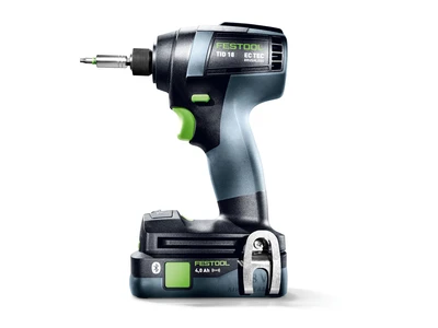
Mounting pull-out drawers
The pull-out drawers are secured in the appropriate holes with Euro screws. The use of bits of 100 mm in length is recommended here.

-
Inserting and fitting drawers
Once all the pull-out drawers have been mounted, the drawers can be pushed in and fitted with Systainers. And this completes the project of building your own Systainer cabinet. Good luck!


-
Our illustrated guides and work results are documented working steps that we have performed in practice. They are individual examples and do not guarantee or promise that users will obtain the same results. The results will depend on the user's experience and skill, as well as the material being used. Illustrated guides do not replace any Festool operating manuals and/or safety instructions. Liability for ensuring that the information, instructions and applications are free from content defects and defects of title, in particular with regard to the absence of defects, correctness, freedom from third party intellectual property rights and copyrights, completeness and fitness for purpose, is excluded. Claims for damages made by the user, regardless of their legal basis, are excluded. These liability exclusions are not applicable if the damage was intentional or caused by gross negligence, or in cases of statutory liability.
We cannot accept liability for damage resulting from defects.↑