


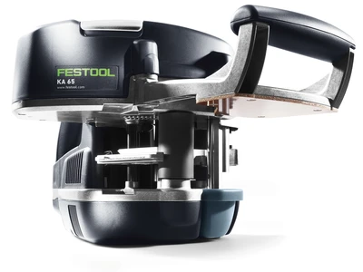


Drilling series of holes with the hole series guide plate for the router

Description
This enables all typical fittings such as:
- Cupboard hinges
- Shelf supports
- Rear wall supports
- Basic structure connectors
- Bearing slides
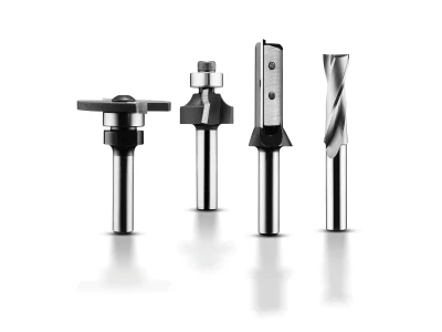
Tools/accessories


Alternative tools
Preparation/set-up
-
Caution:
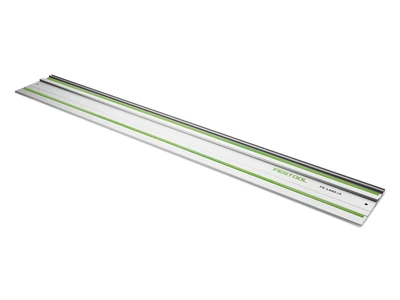
The Festool system for drilling series of holes is designed so that holes are drilled beside the hole series rail. Only the index bolts on the guide plate click into place in the holes for the rail.
Setting the guide plate:
The guide plate must first be set to match the hole series rail without play.
To do so, place the plate onto the hole series rail and click the index bolt into place in one of the holes. Use the two adjusting screws to reduce the play until the plate can smoothly move on the hole series rail with as little play as possible once the detent pin is unlocked.
-
Fitting the router onto the guide plate:
- This action is required for both the OF 1010 and the OF 1400.
- Fit the supplied centring mandrel into the collet of the router.
- Now place the router onto the guide plate and centre it by inserting the centring mandrel into the hole on the plate.
- This position can be maintained by tightening the routing depth clamp until the fixed clamps have secured the base plate of the OF 1010 in place.
- The OF 1400 is screwed onto the guide plate directly via the M6x20 screws.
- Once this has been completed, the centring mandrel can be removed and a dowel hole drill or cupboard hinge drill can be used.

-
Adjusting the parallel side fences:
The parallel side fences must be adjusted initially before initial use. To do so, the adjustable stops on the scales must be positioned at "0" (see arrow).
-
In this state, the parallel side fences are placed onto the hole series rail, the scale clamp is loosened using a 5 mm hex key and positioned so that the stop pin on the parallel side fence fits into the recess of the guide plate.
In this state, retighten the scale clamp. Care must be taken when performing this adjustment, as these scale values are used to set the spacing for the series of holes along the edge of the body later on!
-
The longitudinal stops:
The longitudinal stops are attached to both ends of the hole series rail.
These have different dowel pins for installation underneath the rail, enabling different spacing dimensions to be defined for the position and drilling of the first series of holes.
-
The specifications – which in each case are visible to the user – have the following meanings for drilling the series of holes:
- "32" = first hole positioned 32 mm away from the edge.
- "9.5" = first hole positioned 9.5 mm away from the edge, for instance for eccentric connectors
- "16" = first hole positioned 16 mm away from the edge or precisely in the middle of two holes drilled at a spacing of 32 mm, for instance for cupboard hinges in furniture doors.
- " = " this symbol is visible on the edge of the rail and is used to connect two hole series rails for longer series of holes and to comply with the 32 mm grid dimension


Procedure
-
Drilling the series of holes:
- For the front series of holes for hinged doors, set the adjustable stop to 37 mm and fit it onto the hole series rail.
- Also screw on the longitudinal stop with the required distance from the edges.
- Place the rail and top longitudinal stop on the top edge of the body .
- This is also the reference edge for the rear series of holes that is to be drilled later.
- Now move the rail sideways until the locating pins of the adjustable stops are positioned against the top edge of the workpiece.

-
View from below:
1 = Longitudinal stop
2 = Stop pin for the parallel side fence
3 = Fastening clamp for securing the rails
For accurate results when drilling series of holes, always secure the rails using the fastening clamp.
-
- Place the guide plate with fitted router onto the rail and click the index bolts into place in the first hole.
- Set the required drilling depth and preselect the speed of the router to level 6.
- Now drill the holes, then unlock the index bolt by pressing the rocker on the plate and slide the router forward to the next position.
- This process is used to drill the entire front series of holes.

-
The recess located in the guide plate (see arrow) can be used for drilling groups of holes.

-
This enables, for example, marking and drilling just four holes when drilling a series of holes.

-
The rear series of holes
Example: Fitting bearing slides onto cupboard panels. For this task, the position of the rear series of holes depends on the holes for the bearing slides used.- Set the adjustable stop of the parallel side fence to dimension X.
- The rail is positioned on the same reference edge as for the front and aligned is in parallel to the edge of the workpiece using the set parallel side fences.
- This enables the rear series of holes to now be drilled.

-
Drilling the cupboard hinges into the front of the door:
- A suitable cupboard hinge drill is used to drill the holes into the doors.
A 35 mm drill for common fittings is included with the hole drilling system. - Preselect the speed as level 1–2, depending on the material of the front of the door.
- Take the drilling depth from the fitting and set it on the router.
- Now attach the longitudinal stop so that the "16" marking is visible and therefore drilling can be performed between two holes in a series.
- Simply position the front of the door beside the cupboard panels to mark the desired position of the cupboard hinges.
- Now set the adjustable stops of the parallel side fences such that sufficient material remains
(cupboard hinge D35 mm: 2 = 17.5 mm + 4 mm material thickness in the front of the door results in a setting dimension of 21.5 mm) - Now place the hole series rail on the inner surface of the front of the door and position it on the top reference edge as with the side panels.
The parallel side fences align the rail to be parallel again, and this is then secured in place with the fastening clamp. - The router is now clicked into place using the index bolt via the previously marked position for the cupboard hinge, and the hole is drilled.
- The same procedure is followed for the second cupboard hinge, as well as the third and fourth cupboard hinges if applicable.

- A suitable cupboard hinge drill is used to drill the holes into the doors.


-
Our illustrated guides and work results are documented working steps that we have performed in practice. They are individual examples and do not guarantee or promise that users will obtain the same results. The results will depend on the user's experience and skill, as well as the material being used. Illustrated guides do not replace any Festool operating manuals and/or safety instructions. Liability for ensuring that the information, instructions and applications are free from content defects and defects of title, in particular with regard to the absence of defects, correctness, freedom from third party intellectual property rights and copyrights, completeness and fitness for purpose, is excluded. Claims for damages made by the user, regardless of their legal basis, are excluded. These liability exclusions are not applicable if the damage was intentional or caused by gross negligence, or in cases of statutory liability.
We cannot accept liability for damage resulting from defects.↑