


routing cutouts using MFS multi-routing templates

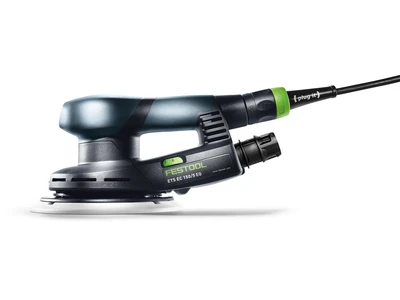
Description
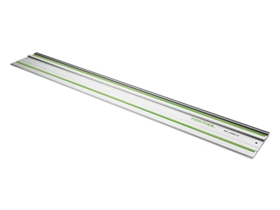
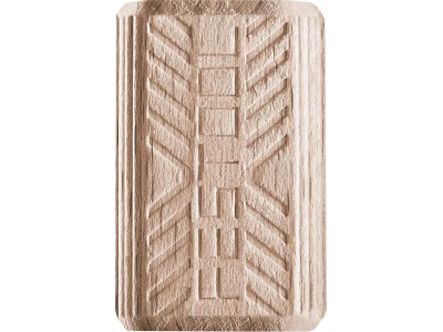
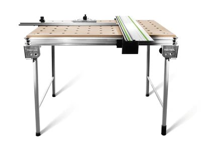
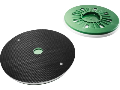
Tools/accessories
Alternative tools
Preparation/set-up
-
The dimensions of the air vent must firstly be determined. To do this, the following procedure is suggested:
The multi-routing template is easiest to adjust if only the screws in diagonally opposite corners are either loosened or tightened. This allows template movement in only one direction.
The leg must be adjusted so that the air vent can be properly inserted into the frame.
-
The corresponding length and width dimensions can then be read from the scale on the aluminium profile (see image).
Calculating the setting dimension:
To calculate the setting dimension, the dimensions of the air vent (length and width) are determined; the cutter diameter is subtracted from the copying ring diameter and the result is added to each of the air vent dimensions.
Example:
Air vent length 430 mm, width 76 mm
Copying ring diameter 30 mm – cutter diameter 20 mm = allowance 10 mm
Routing template setting:
Air vent
Length 430 mm + 10 mm = setting dimension 440 mm
Width 76 mm + 10 mm = setting dimension 86 mm
In our example, we add 2 mm for play. This gives a setting dimension of 442 x 88 mm.
-
Setting:
- Select the calculated setting dimension on the routing template. First, as described, loosen the two diagonally opposite fastening screws, set the desired width and tighten again.
- The longitudinal dimension is set in the same way using the two other diagonally opposite fastening screws.
- Now mark the position of the air vent including the allowance on the workpiece; this enables the cut-out to be routed later.

-
Position the multi-routing template on the workpiece and adjust to the markings.
Important: Before routing, always fasten the template with clamps.


Procedure
-
The copying ring, cutter and extractor are mounted on the router according to the guide.
Set the routing depth using the turret stop.
Set the speed to 6.
Switch on the machine and insert it into the workpiece to the set routing depth on the turret stop.

-
Guide the router with the copying ring clockwise (counter direction) along the multi-routing template until the starting point is reached.
Rout the opening into the workpiece in two or three work steps.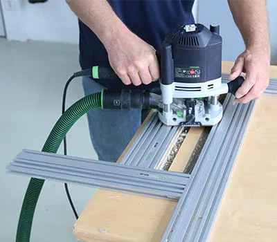
-
Tip: When routing a larger cut-out, the router may tip over. The tilt protection among the items included with the MFS prevents this from happening. To do this, all users need to do is insert the copying ring being used into the corresponding segment in the tilt protection, then rout the cut-out.

-
The result: A cleanly routed air vent cut-out that is produced easily and efficiently using the Festool system.


-
Our illustrated guides and work results are documented working steps that we have performed in practice. They are individual examples and do not guarantee or promise that users will obtain the same results. The results will depend on the user's experience and skill, as well as the material being used. Illustrated guides do not replace any Festool operating manuals and/or safety instructions. Liability for ensuring that the information, instructions and applications are free from content defects and defects of title, in particular with regard to the absence of defects, correctness, freedom from third party intellectual property rights and copyrights, completeness and fitness for purpose, is excluded. Claims for damages made by the user, regardless of their legal basis, are excluded. These liability exclusions are not applicable if the damage was intentional or caused by gross negligence, or in cases of statutory liability.
We cannot accept liability for damage resulting from defects.↑