


Routing recessed grip for drawers or furniture doors

Description
Drawers behind a cabinet door inside a cupboard, in particular, are often provided with such grip recesses because usually there is not enough room for fitted handles. The dimensions of the hand hole cutter are suitable for workpieces that are at least 18 mm thick.
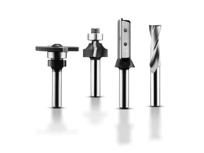
Tools/accessories
Alternative tools
Preparation/set-up
-
The following preparatory work must be carried out before routing a recessed grip:
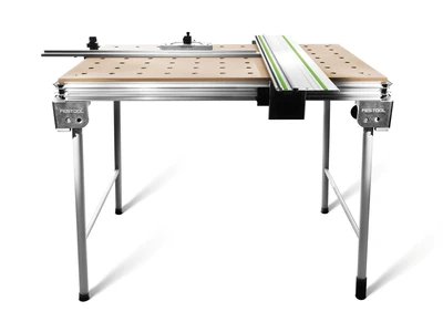
Secure the workpiece on the multifunction table (MFT). To do this, place the workpiece on a supporting pad.
Ensure that the inside of the drawer front, or furniture door, bears correctly on the table, i.e. the front side faces upwards.
Secure the workpiece with the clamp clips; ensure that the clamp clips do not interfere with the routing operation.
-
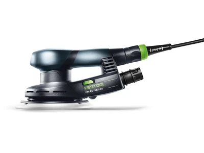
Adjust the router as follows for the routing process:
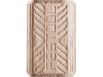
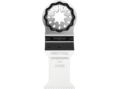
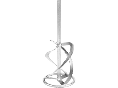
Clamp the hand hole cutter in the chuck of the router; the router shaft should be inserted and clamped up to the minimum clamping depth in the chuck.
Lower the router until the cutter rests on the workpiece. Use the depth setting to set a routing depth of 16 mm for the recessed grip.
Secure the parallel side fence and set it so that it is aligned with the outermost round edge of the cutter. Mark this point with a pencil on the router table. Now push the parallel side fence back until it is 8–10 mm behind the drawn line.


Procedure
-
Proceed as follows when routing:
Place the router on the workpiece to be routed and move it downwards. Secure the locking screw to fix the depth of the router. Ensure that the tool does not touch the workpiece when it is turned on.
Now switch on the tool and move the cutter slowly into the workpiece. Move the tool from left to right, i.e. in reverse direction.
-
During the routing process, ensure that the pressure on the workpiece is initially applied to the right-hand surface of the parallel side fence as long as the left surface has no support. When the left surface does have support, distribute the pressure across both surfaces of the parallel side fence. As soon as the right-hand surface has no more support, redistribute pressure to the left-hand surface of the parallel side fence. This is the only way to rout a recessed grip without creating "waves".
When you reach the end of the drawer or furniture door, you can switch off the router. However, do not move the router from the workpiece until it is stationary.

-
To route an inset recessed grip that does not go all the way through the material, mark the start and end of the groove; insert and remove the router at these points. For this purpose, mark the limiting lines approx. 8 cm so that you can move along these lines with the notch on the other side of the router table.


-
Our illustrated guides and work results are documented working steps that we have performed in practice. They are individual examples and do not guarantee or promise that users will obtain the same results. The results will depend on the user's experience and skill, as well as the material being used. Illustrated guides do not replace any Festool operating manuals and/or safety instructions. Liability for ensuring that the information, instructions and applications are free from content defects and defects of title, in particular with regard to the absence of defects, correctness, freedom from third party intellectual property rights and copyrights, completeness and fitness for purpose, is excluded. Claims for damages made by the user, regardless of their legal basis, are excluded. These liability exclusions are not applicable if the damage was intentional or caused by gross negligence, or in cases of statutory liability.
We cannot accept liability for damage resulting from defects.↑